USS Yorktown CV-5 Revell 85-3017 Review

RoR Review 20110705* – USS Yorktown CV-5 Revell 85-3017 Review
Â
Review and Photos by Lonny Dyer   Â
 Â
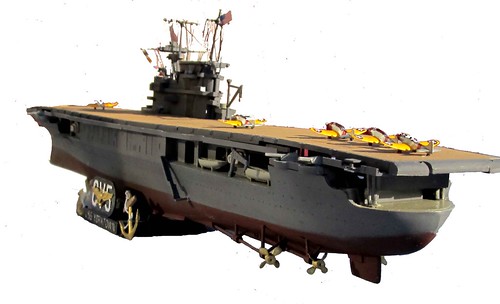
USS Yorktown (CV-5) was commissioned in the United States Navy from 1937 until she was sunk at the Battle of Midway in June 1942. She was named after The Battle of Yorktown in 1781 and was the lead ship of the Yorktown class which was designed after lessons learned from operations with the large converted battle cruisers of the Lexington class. She represented the epitome of U.S. pre-war carrier design.
For the modeler – this 1:485 scale Revell kit provides an excellent representation of the USS Yorktown. it contains 114 pieces molded in gray, 1 sheet of ensigns to fly off the rigging, 20 Douglas Dive Bombers, and a few decals. The finished model is over 20 inches long and contains many details. The kit also contains 2 separate name plates, the Yorktown and the Hornet. But there are no design differences in the instruction sheet to accurately reproduce the Hornet. Altered construction sequence and some scratch building are offered here to produce a great looking model of the USS Yorktown.
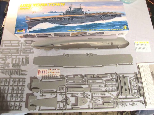
Figure 2 Parts layout
The hull and flight deck are both solid one-piece designs which enhance the appearance of the final build. Notice the thickness of the sprues compared to the actual pieces, a sharp knife is definitely required to remove the pieces from the sprues.
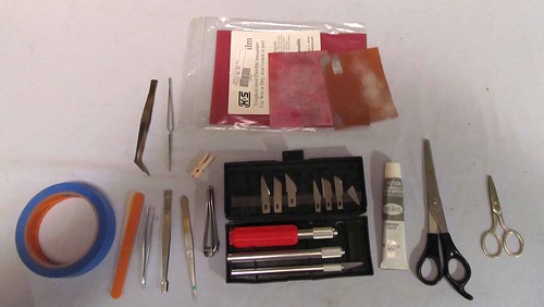
Figure 3 Tools required
Above is some of the equipment needed to construct this kit.
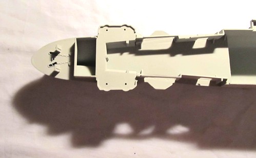
Figure 4 Forward hull and deck assembly
These pieces line up really good for assembly but will require some filler to hide the seams. The forward hull assy. after filling and sanding smooth the gaps between hull and deck and the bulkheads to deck. Take care to set your bulkheads straight as these attach to the flight deck later!
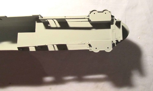
Figure 5 Rear hull and deck
As in the front assembly, when building the rear deck, filler is needed where the deck meets the hull. Also watch that your bulkheads stand straight so they will align with flight deck later. Now would be the time to do any detailing you wish to do to the hanger deck. Besides mounting aircraft, you could fabricate and install doors behind some of the openings, or build lift assemblies if you plan on cutting out the elevators on the flight deck and having them in a lowered position.
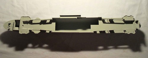
Figure 6 All decks mounted to hull primed and painted.
I finished steps 1 and 2, and then primed with Duplicolor grey primer and painted the deck floor with Tamiya Light Grey (flat). The only concern with my method is you will have to mask off these decks when you paint the hull and vertical bulkheads but it was worth the extra time to get the finish I wanted for the hanger deck.
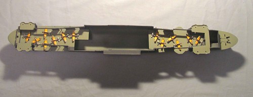
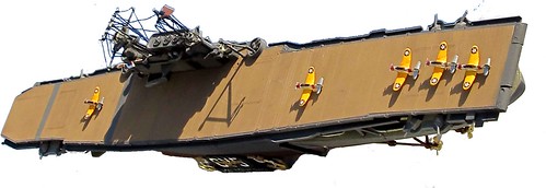
Figure 7 Planes on hanger deck
At this time I painted my aircraft so that i could mount some of them here on the hanger deck as I wasn’t going to mount all 20 on the flight deck.
** Please Note**Â if you are going to cut out the elevators when building the flight deck do not position aircraft where they will block the elevators!!
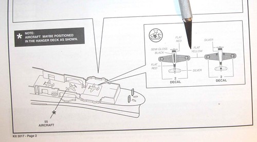
Figure 8 Instruction error #1 Decals for planes
The instructions show two decals on both the top and bottom of the wings on each aircraft BUT there are only 40 US emblems for 20 planes on the decal sheet. I just put them on the tops of the wings because in my display the bottoms of the wings will not be visible.
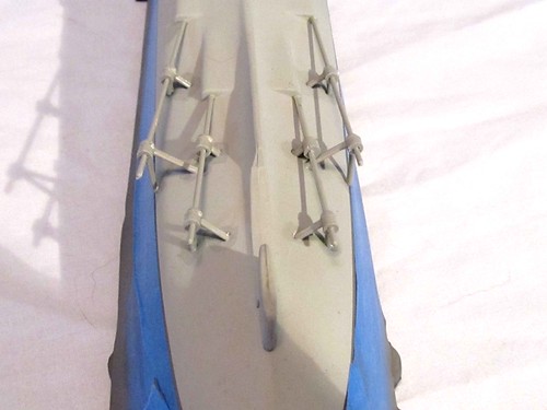
Figure 9 Install prop shafts
Step 3 Installing the prop shafts and supports prior to painting the hull bottom ensures better adherence and prevents staining the hull paint with cement. Pay attention to the support struts numbers and locations as these pieces are not interchangeable. Also if you do not get these on straight your shafts will show a bend in them when finished.
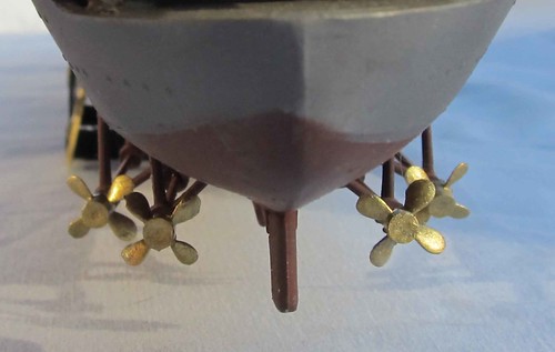
Figure 10 Prop shafts after painting
Because the propellers are so fragile, I recommend not placing them till the build is completely done. It does not take much to break a blade off. I learned that from experience.
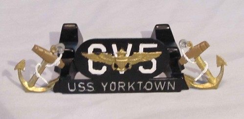
Figure 11
The stand assembly after painting.
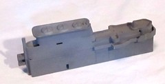
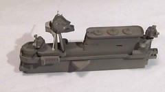
Figure 12 & 12a Building the Island
The island goes together real well, although there are a few gaps left that are difficult to fill and sand.
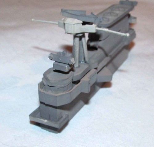
Figure 13 Part 2 of the island assembly
Before you mount the island and the deck details now would be a good time to assemble the flight deck to the hull. See picture below, with the flight deck upside down apply cement to the outside of the guides (8marked with red) and then place your hull onto it. line the bulkhead walls with your glue stripes and you should have no problem.
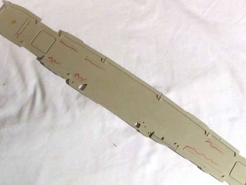
Figure 14
Location points to apply cement to mount flight deck
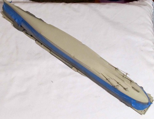
Figure 15 Hull mounted to flight deck
Now you can mount the island and the remaining deck details.
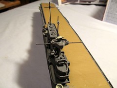
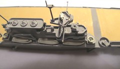
Figure 16 & 16a Mounted island
With your masts installed and allowed to dry and set up now is time to put the riggings on the masts. The only problem is that there is no clear guide on how to mount them and the forward mast does not have the crossbar as depicted in the instructions and on the box art (see pictures above and below).
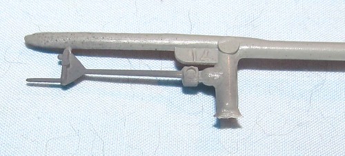
Figure 17
This is the actual mast you receive in the kit.
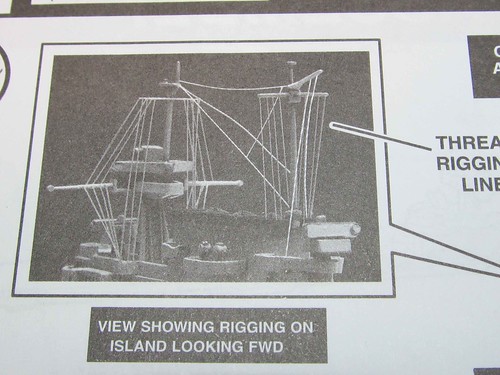
Figure 18
Instruction sheet showing crossbeam on mast
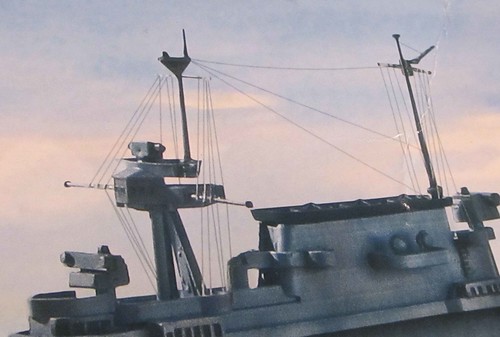
Figure 19
Box art showing crossbeam on forward mast
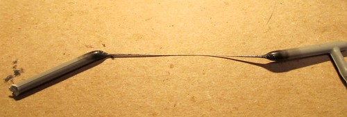
Figure 20 Making a crossbeam for the mast
This is how I made a crossbar to mount on the mast to try to replicate the correct rigging. Slowly heat a piece of sprue, and gently pull it to stretch out a piece to use as the crossbeam on the forward mast. it took a few tries to get one just the right diameter that would hold shape while attaching the rigging. Your beam must be thick enough that it will not bend, but try to be small enough to stay in scale.
As a WWII buff, this was an exciting kit to build. For its scale it has many nice details and the finished product is a great addition to my collection. It is rated at level 2 and for the most part that may be a little high. but the rigging and the difficulty getting pieces off the sprues due to the thickness of the sprues compared to the pieces requires patience and a very sharp knife to remove them overall I too rate it at level 2..
*All Registered trademarks are the property of their respective brands.