RoR Review 20100820 – Revell 85-1865 Star Warsâ„¢ Republic Gunshipâ„¢

RoR Review 20100820 – Revell Star Warsâ„¢ Republic Gunshipâ„¢
Â
Buy This Kit
This kit comes in an oversize box and has some great box art. Inside the box are six (6) parts sprues and six action figures, with a total of 49 parts (including the figures). The sprues are bagged or not adjacent so the parts can’t scratch each other. None of the parts in my kit were damaged. That’s important because these parts are pre-decorated
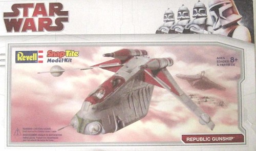
Figure 1
This kit went together easily and the parts fit together as they should. Glue is not required but on some of the parts like the fuselage halves or laser gun nacelles it can help eliminate tiny gaps and keep the internal parts correctly in place.
The eight-page 8 ½ x 11 instruction sheet has eight simple to follow phases. Although the instructions are pretty simple there were a couple things that are better understood with the photos of the actual pieces as they are going together and there was one error that will be identified. Assembly time can be done in around an hour and even if you’ve never built a model before you should be able to get this kit on the display stand in an evening.
Assembly:
           Put together the rear laser canon per the kit instructions and slide it into the left fuselage half as shown in Figure 2.
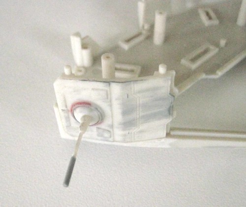
Figure 2
There is an error in the instructions related to part #19 (an exterior (exhaust?) panel). The instruction indicates that the panel is mounted to one of the large fuselage posts (circled). Ignore this instruction and slide the panel into the recess at the back of the fuselage shown by the red arrow in Figure 3.
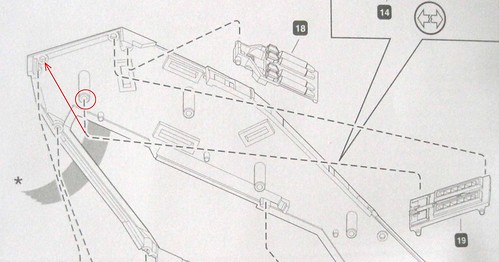
Figure 3
Correct placement of the exhaust panel (part #19) is shown in (see figure 3a).
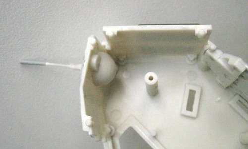
Figure 3a
      Figure 4 shows the orientation of the troop grab handle rack (part # 15) and the other panels inside the fuselage at step 2.
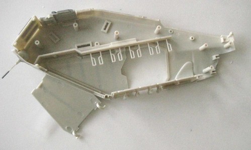
Figure 4
Sub-assemble the cockpit and flight crew figures as per the instruction sheet. Use a narrow implement like the blunt end of a paint brush or pencil to snap the seat buttons into place then insert the pilots (parts #5 & 9) last. Slide the cockpit sub-assembly into place Figure 5.
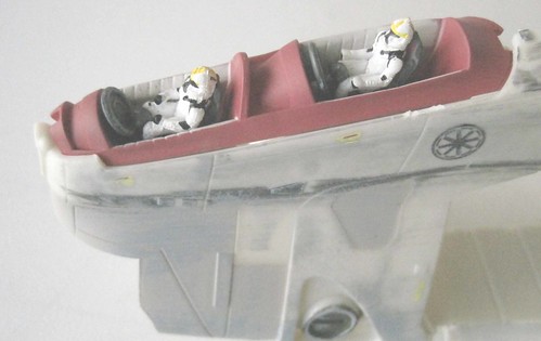
Figure 5
      Add the canopy to the cockpit assembly Figure 6.
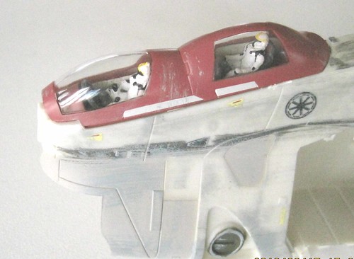
Figure 6
      If you missed it in Step 1 there is a callout graphic in the upper right that indicates
removal of these sprue runners by wiggling them back and forth Figure 7. You’ll notice it at this point because you won’t be able to install the fuselage bottom panel (part #17) in Step 2.
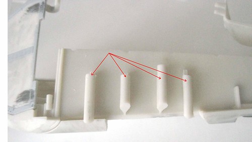
Figure 7
      Here are the witness marks left over after those runners are removed Figure 7a.
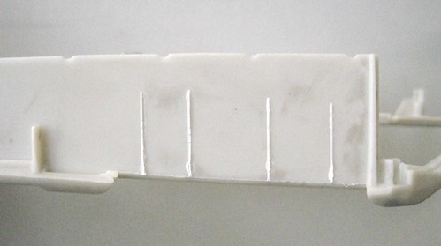
Figure 7a
Below is the fuselage half (part #14) with all the panels and sub-assemblies in place from the inside view (Figure 8).
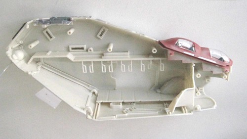
Figure 8
Shown here is the fuselage half (part #14) with all the panels and sub-assemblies in place from the outside view (Figure 9). Note that the moveable panels are held in place by clear tape to keep them there until the fuselage halves are put together.
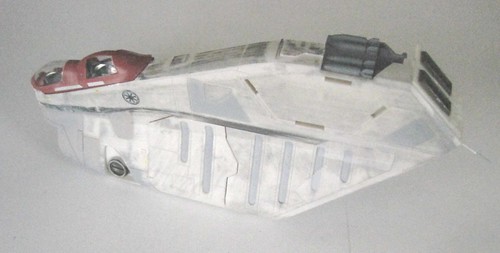
Figure 9
      Step 3 includes assembly of the other fuselage half (part #20) and commences much in the same way but is minus the canopy and panels that are attached to the other side. Again, tape the moveable panels in place until the fuselage halves are joined together (Figure 11).
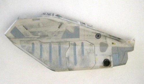
Figure 11
Carefully align the two halves in Step 4 by matching the panel recesses and joining posts together, then firmly press the two halves together until they mate up to each other Figure 12.Â
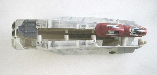
Figure 12
Sub-assemble the two engines by pressing them together. This is one of those places where a little glue comes in handy to eliminate small gaps in the seams Figure 13.
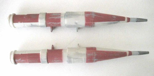
Figure 13
On the main wing parts I found the only real faux pas in the pre-decorated parts. The rocket racks, which appear to be hand painted, can use a little touch up with some medium gray paint between the weapons (Figure 13a). This might vary from kit to kit.
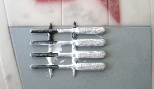
Figure 13a
      Complete the wing sub-assembly in steps 5 & 6 and align the wing tabs to the fuselage halves Figure 14.
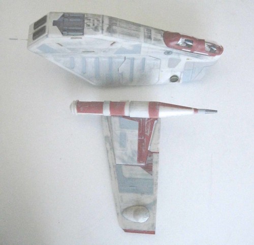
Figure 14
Attach them to the correct fuselage halves as shown in Figure 15. Again, a little glue applied to the tabs and recesses in the fuselage will add some strength to this assembly point and ensure that there aren’t any gaps in the future.
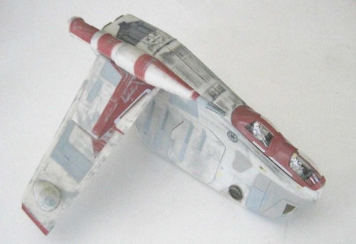
Figure 15
      Align and attach the other wing assembly in the same manner to complete Step 6 Figure 16.
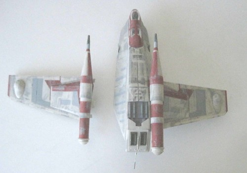
Figure 16
In Step 7 the forward laser canons are assembled but the diagram isn’t clear about orientation of the nacelle. This is a keeper that is installed after the guns are in place. Just make sure that the wide part of the keeper plate is at the bottom as in Figure 17.
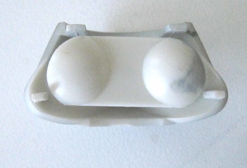
Figure 17
      Prior to assembly of the forward canons I decided to add a little weight to the front end of the model. This is because when the model is placed on a flat surface (to simulate a troop drop) and the rear hatch is down the model is pretty tipsy wanting to rock backwards. Adding a small pipe plug (Figure 18) solves the issue. Note that the model is upside down here.
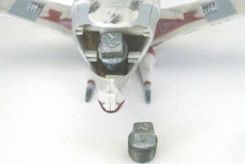
Figure 18
      Now keep the model upside down then align and press the forward canon assembly into place to seal in the added weight in Figure 19.
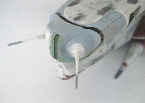
Figure 19
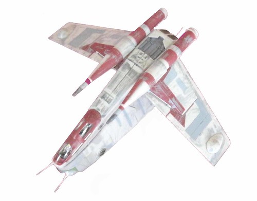
You can also assemble the display base which is pretty well balanced for the model even with the added weight in the front to complete Step 7. In Step 8 Figure 20 shows the finished model in ground assault mode with troopers descending the hangar door platform and emerging from the sliding side hatch. This realistic looking model conveys the action and excitement of the Star Wars theme and makes a great project and collectible for both the novice and experienced modeler.
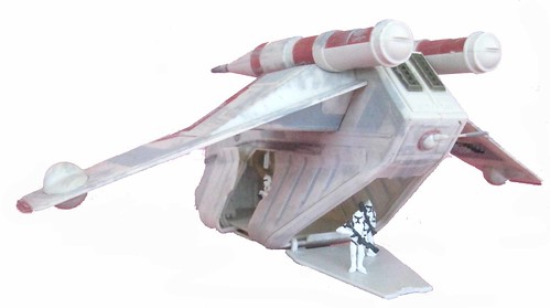
Figure 20
Finished Dimensions:
Length: 9-7/16″ Wingspan: 9-3/4â€Â Height: 6-3/4†on stand
Pros:
This is an easy model to build that looks great out-of-the-box but has potential for serious modelers with the addition of weathering and additional detail. Parts are free of flash and fit together very well.
Cons:
Some instructions are not very clear and some glue would be useful to close minor gaps.