Star Wars Tie Fighter Revell kit 85-1875 Review

RoR Step-by-Step Review 201202##* – Star Wars Tie Fighter Revell kit 85-1875 Review
Click Here to Buy This Kit

Review and Photos by Doug Cole 
 My eight year old son recently spotted a Star Wars kit in my stash and enthusiastically asked if he could build it. It’s a SnapTite kit so I happily agreed. This kit has been out for a while but has recently been re-released so I decided to chronicle the build as a consultant/observer. I must say that I was pleasantly surprised at the ease of construction and the good overall quality of this kit. My son was easily able to follow the instructions and assemble the kit by himself. The best part was that he was pleased with the  results and gained more confidence as a model builder even when I tossed in some intermediate finishing techniques for him to try out. If you have a youngster – this is a great kit for them to build.
 For the Modeler: Some attention to removing sprues and some minor flash are about all the added work needed to make this a kit that a youngster can be proud of. The addition of some blackwash for bringing out the detail and adding a little “battle-tested†appearance just helped to bolster the aura of this model. There’s a couple spots that don’t snap together just right so keep a little glue handy straighten that out along the way. For the Star Wars fans – this would be a nice addition to your collection.
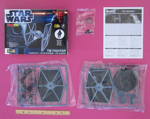
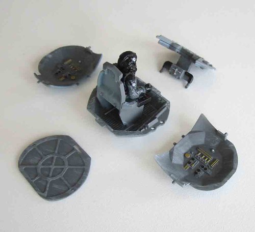
001 The kit and its contents.
 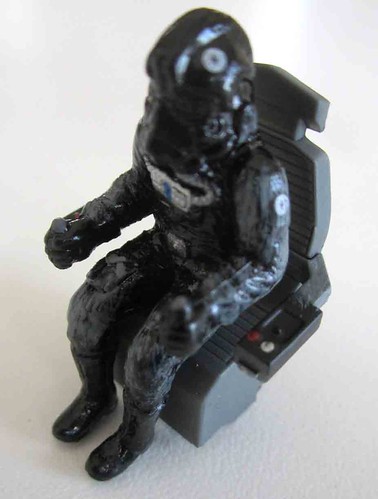
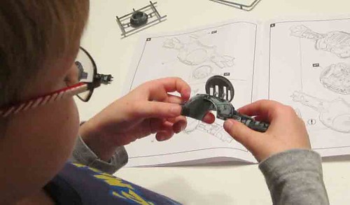
002 In Step 1 you assemble the pilot, seat and armrest controls like this. The parts are all pre-decorated so they just snap together.
Â
003 Step 2 – Assemble the forward bulkhead, consisting of the inner and outer panels along with some control arms.
 Â
O04 In Step three you assemble the command module including the forward bulkhead and seated pilot’s assembly as well as the outer walls and the rear bulkhead. The rear bulkhead has a slot and tab to help with alignment and the two side walls are identical so they can go on either side with the posts and holes for their positions.
Â
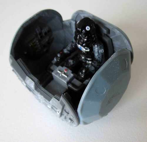
005 This is the completed sub-assembly
006 At Step 4 you’ll assemble the top access hatch for the fighter and it was here that I found the only part with any real flash on it. It is easily removed with a hobby knife. The post in the back is not part of the fixture. It must be removed and the three pieces assembled into the hatch panel module.
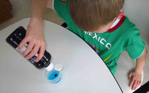
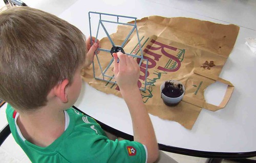
007 It was at this point that I determined that some blackwash should be applied to the model while most of the parts were still on the sprues. That makes it easier to handle. I use a simple formula of three equal parts water, dish soap and black acrylic paint for this. I felt that the Maui Blue color the parts are molded in would just look a little more realistic if they could be toned down a bit. My son had fun mixing up the “juice†for this step.
Â
008 Apply the juice to all the exterior surfaces of the model and let it dry at least overnight.
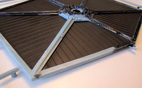
009 You can see that there is quite a bit of difference in tone between the raw plastic color and the black washed part. I imagined our Tie Fighter with a little “stellar dust†on it stuck way out there with few fighter wash stations to keep it clean.
Â
 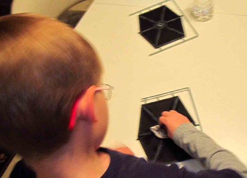
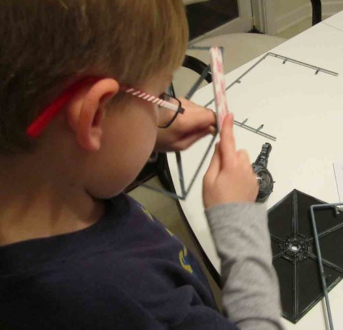
010 After the parts are dry use a damp soft cloth to rub off some of the blackwash to reveal some of the relief detail on the parts.
Â
011 In Step 5 begin by assembling one of the halves of the main module and spoke assembly. Here the access hatch is placed into the upper half portion.
 Â
012 The lower half contains the two bright orange weapon pods. The one seen here on the left side didn’t want to stay so a little adhesive was applied to keep it in place.
013 Here are both assembled halves of step 5
 Â

014 In Step 6 you’ll put the whole center spoke together with the pilot’s command module. Start by putting the forward windshield into place by locating the key on its edge that fits into the slot on the main section.
Â

015 Do the same with the engine plate at the rear and then snap the pilot module into place in the center.
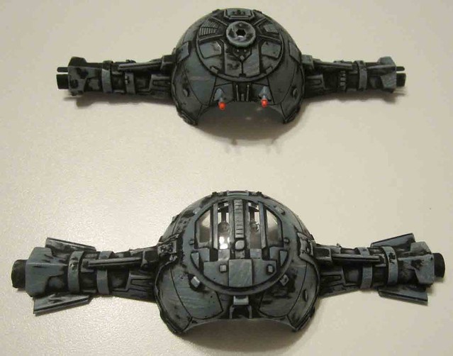
016 Finally, place the top half over this and line up all the posts and holes. Gently squeeze the two halves together until all the seams are joined. I was happy that this portion went so well and assembled flawlessly.
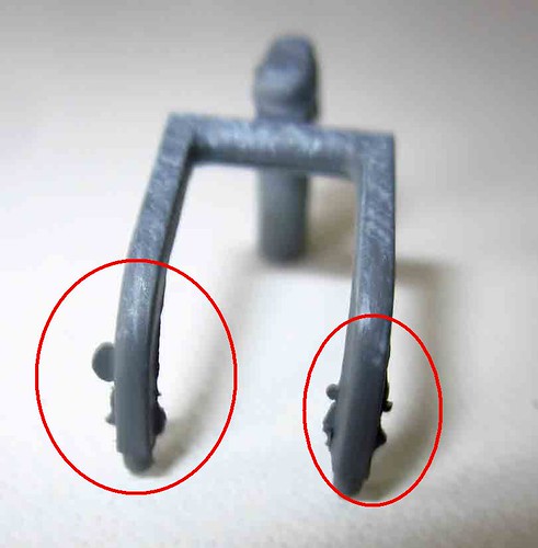
017 Next remove the stabilizer panels from the sprues. It turns out this step is important because the attachment points are heavy and need to be trimmed as close to the parts as possible.

018 Here are some of the very heavy sprue attachment points.

019 In Step 7 assemble both outer stabilizer panels by lining them up and snapping them together. It seemed to be easier to do this by laying the parts down on the table.
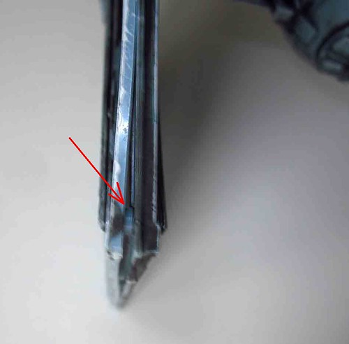
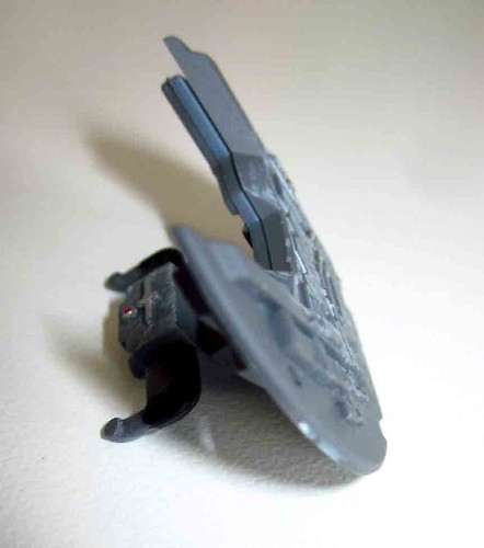
020 I only found one point that would not stay snapped. The forward lower corner needed a little glue to stay closed. You can see the post in this photo because the edge of the wing would not snap into place and stay.
021 You’ll have to file off any sprue attachment points that are left on these “wings†and struts after you remove them from the sprue.
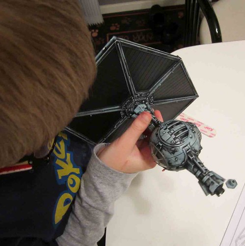
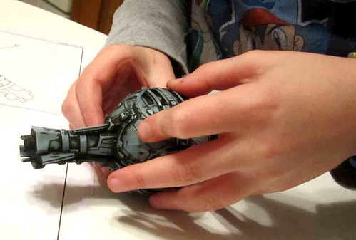
022 After the stabilizers are assembled It doesn’t appear to matter which one goes on which side, but the stabilizers are taller than they are wide. It helped to pinch the end of the spoke a little to get it inserted into the hex shaped opening in the stabilizers. Make sure to seat it all the way and then use the tee (part #26) to snap into place on the outside of the “wingâ€. This made for a tight retainer that keeps the center spoke in place but was easy to install.
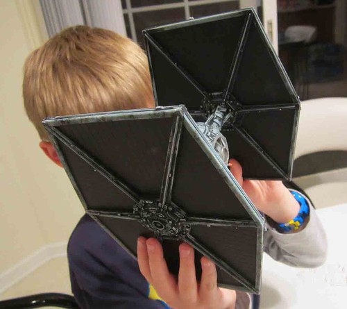
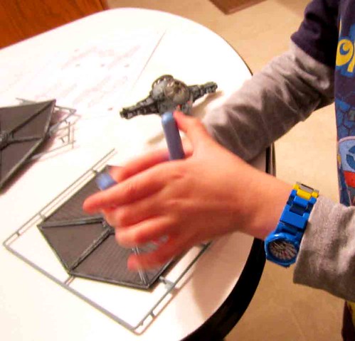
023 Repeat the process on the other side and an you have completed your Tie Fighter assembly.
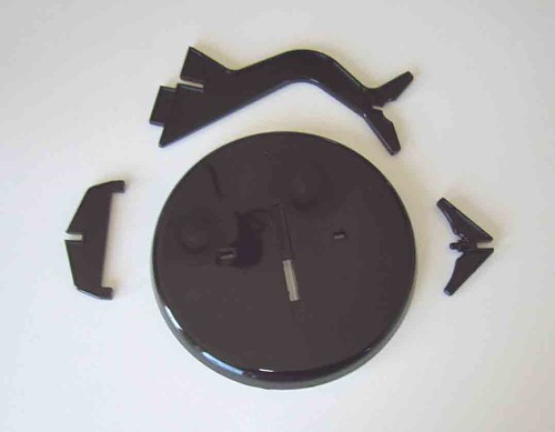
024 Round up the parts for the display stand.
 Â
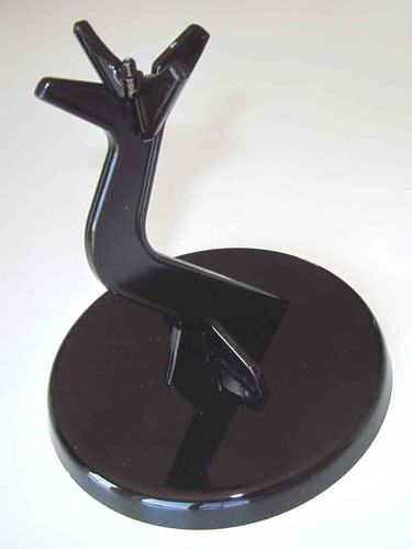
025 In Step 8 the four pieces only go together one way and they make an attractive stand for your latest Star Wars model
 Â
*All Registered trademarks are the property of their respective brands.
Â
Â
Â
Â
Â
Â
Â
Â